
Mini Spider Crane Selection for Confined Job Sites
Mini Spider Crane Selection for Confined Job Sites
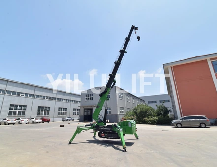
A mini spider crane is useful when a conventional mobile crane cannot get close enough to the lift, but compact dimensions do not make every small crane suitable for every restricted site. The choice must connect four things: the load, the working radius, the access route, and the space and ground available for the outriggers.
For an early shortlist, buyers should measure the route and setup area before choosing a tonnage class. YILU LIFT can then review the load, reach, height, access, power, and site conditions against a relevant model and provide a quotation for the proposed configuration.
Define the Lift Before Comparing Crane Sizes
Describe the load, not just its weight
Start with verified weight, dimensions, center of gravity, lifting points, and any rigging or below-the-hook attachment. A compact load close to the crane is different from a long frame or glass panel that must be controlled around a façade, machine, wall, or ceiling.
The nominal capacity is only a model-class reference. Available capacity changes with working radius, boom configuration, hook arrangement, and the conditions stated in the applicable model information. Never combine the maximum rated load with the maximum reach or lift height as though all three occur at the same time.
If the lift uses a vacuum lifter, spreader, lifting beam, or other attachment, include its weight in the project information. The crane carries the complete suspended arrangement, not just the payload that will remain in the building.
Fix pickup and placement geometry
Record pickup height, placement height, horizontal distance from the crane’s planned center of rotation, and the maximum radius reached during the movement. Add nearby walls, roof edges, ceilings, pipes, scaffolding, machinery, and other obstacles that affect boom position.
A simple plan view and side view can be enough. They do not need to be engineering drawings at the first enquiry stage. Clear dimensions help YILU LIFT understand whether the project is mainly constrained by capacity, reach, height, access, or setup space.
Measure the Complete Access Route
Check the narrowest point
Measure gates, doors, corridors, lifts, ramps, turns, and the final approach. Width alone is not sufficient. Height, floor condition, slope, turning space, and any threshold or change in level can decide whether the crane reaches the setup position.
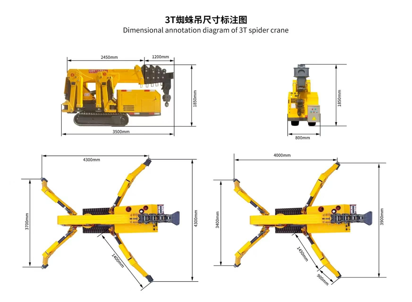
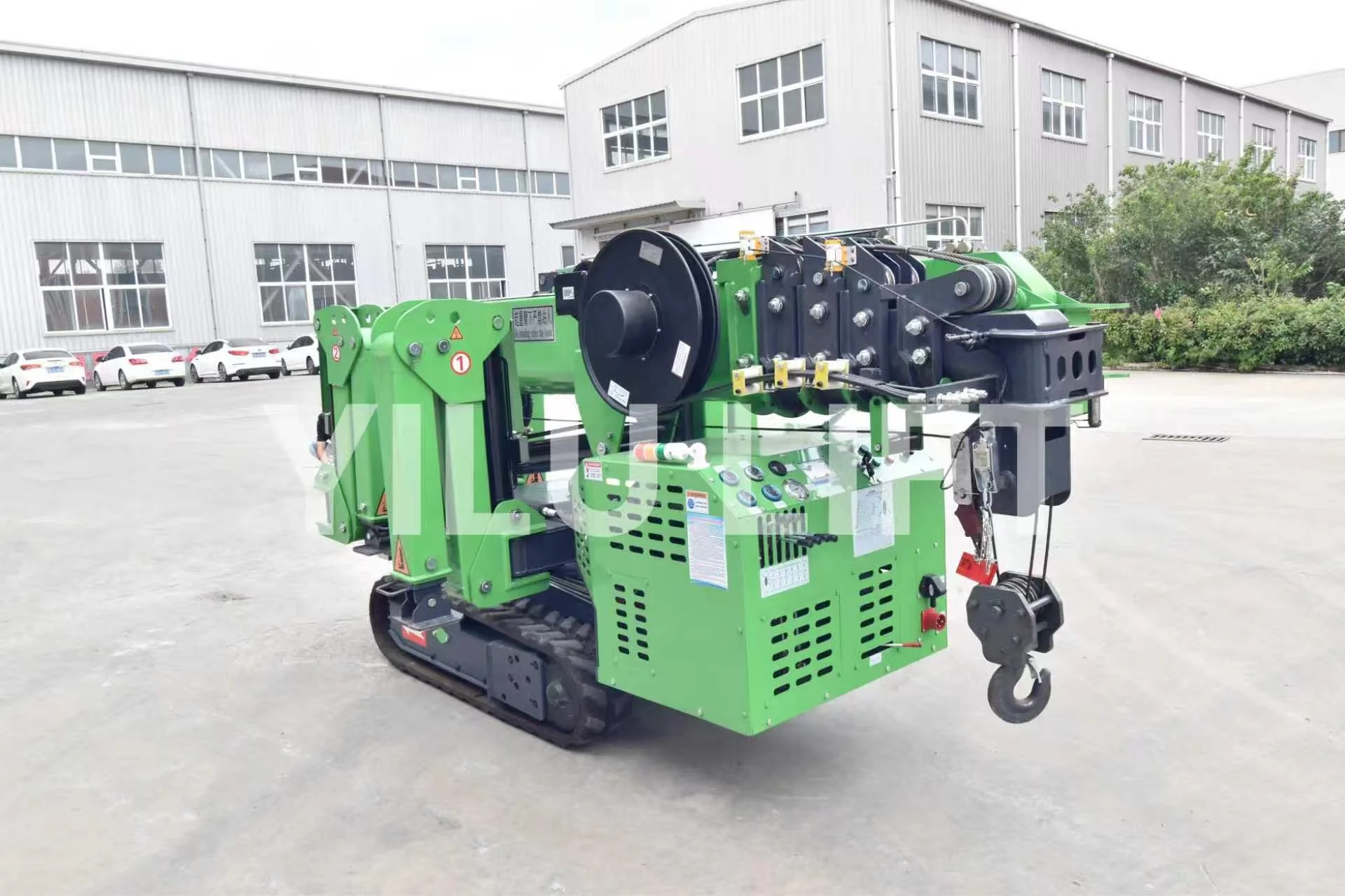
The YILU LIFT CL3.0 crawler spider crane has a published folded size of 3.5 × 0.8 × 1.85 m and a dead weight of 2,700 kg. Those values make it possible to screen transport and access before discussing the lift itself. They do not replace a route check or confirm that a particular floor, ramp, or lift can carry the machine.
Plan transport separately from lifting
The transport plan should cover how the crane reaches the site, how it is unloaded, where it travels, and where it can turn. Indoor routes may also require attention to floor protection, ventilation, and the selected power source. Rooftop or elevated-floor work needs a separate review of how the machine gets there and whether the supporting structure is suitable.
Do not assume that fitting through the door completes the access study. The crane must still reach a usable setup position with enough room to deploy outriggers, slew, raise the boom, and handle the load without creating a new obstruction.
Reserve Space for the Outriggers
Compact travel width is not the working footprint
Spider cranes travel with their outriggers folded. During lifting, the outriggers extend to create a stable base. The setup footprint is therefore larger than the transport envelope and must be checked against walls, columns, trenches, kerbs, stored materials, pedestrian routes, and traffic lanes.
Mark the proposed crane center and each outrigger contact area on the site plan. This makes conflicts visible before delivery. If full deployment is restricted, the applicable model data and planned configuration need specific confirmation; a buyer should not assume that every partial setup supports the same lifting performance.
A client-supplied 3-ton dimension drawing shows a transport envelope of 3.5 × 0.8 × 1.85 m. The same sheet illustrates two outrigger layouts with furthest labelled overall extents of approximately 4.3 × 4.3 m and 4.0 × 3.9 m. Use the drawing as a space-planning reference for the shown machine and layout; it does not replace the applicable load chart or setup instructions.
Treat the ground as part of the lift
Each outrigger transfers force into a relatively small area. Concrete slabs, suspended floors, block paving, compacted ground, backfilled trenches, and soft soil do not behave the same way. Surface appearance alone cannot confirm adequate support.
Provide the known ground or floor description and flag basements, voids, drains, edges, recent excavation, or unknown construction. Suitable mats or load-spreading measures may be required as part of the lift plan. Final ground assessment and setup should follow the applicable site procedure and qualified lift planning.
Match Reach and Height to the Real Working Radius
Use published figures for early screening only
The CL3.0 page lists a 3-ton class, a maximum operating radius of 10.5 m, and a maximum ground lift of 10.8 m. It also lists a six-section boom with a 3.1 to 9.2 m boom-length range. These figures describe the model’s overall envelope and help identify whether it deserves closer review.
They do not show the allowable payload at every radius and boom position. The next step is to provide the planned lift geometry and request confirmation against the applicable model information. This keeps early product comparison useful without turning separate maximum figures into an unsafe assumption.
Leave room for practical positioning
The minimum theoretical radius is rarely the only concern. Installers may need clearance for rigging, tag lines, façade edges, the load itself, and final alignment. The crane position may also need to move away from weak ground, a buried service, or a blocked access lane.
Build that practical distance into the sketch. A model that only works at the most optimistic crane position may be a poor site choice even if the headline figures look adequate.
Choose Power and Controls Around the Site
Indoor and low-emission work
Indoor projects often place more emphasis on ventilation, noise, available electrical supply, and cable routing. The CL3.0 page lists diesel and AC as standard configuration and states that AC voltage can be customized. Buyers should provide the destination voltage and frequency and describe whether the machine will travel or lift indoors.
Power selection should be discussed alongside the working cycle. A project may involve short positioning moves followed by repeated lifts at one station, or continuous movement between several areas. The better configuration is the one that fits the site restrictions and operating pattern, not simply the longest list of power options.
Operator position and visibility
Confined work can place the operator close to walls, columns, or the load path. State where the operator can safely stand and whether the load is visible throughout the movement. The public CL3.0 information lists manual operation and walking. Any requested remote-control or monitoring option should be confirmed for the proposed model rather than assumed from another crane.
Compare Models by Project Fit
Smallest is not always most practical
A smaller crane may pass through a tighter route, but it may require a closer setup position or offer less capacity at the required radius. A larger unit may create the opposite trade-off. Compare the complete job: delivery, travel, setup, lifting, repositioning, and removal.
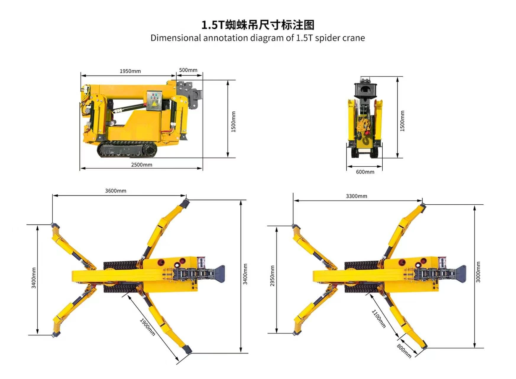
A client-supplied 1.5-ton drawing lists a transport envelope of 2.5 × 0.6 × 1.5 m. Its two illustrated outrigger layouts reach approximately 3.6 × 3.4 m and 3.3 × 3.0 m at their furthest labelled extents. This is useful for early model comparison, but the exact outrigger position and lifting capacity must still match the selected machine and lift plan.
The YILU LIFT crane product category gives buyers a place to review available equipment families. For a meaningful shortlist, send one consistent project brief and ask for the models that can be considered under those same conditions.
Avoid price comparisons between unlike configurations
A useful quotation comparison should keep the load, radius, height, power, controls, optional equipment, destination requirements, and documentation scope consistent. Otherwise, a lower price may simply reflect a different configuration or a machine screened for a different task.
Ask what is included with the proposed crane and which project inputs still need confirmation. This keeps the commercial discussion tied to a workable lift rather than a tonnage label alone.
Common Mini Spider Crane Selection Mistakes
Measuring the door but not the turn
A crane can pass the narrowest opening and still fail at a corner, ramp, lift entrance, or setup approach. Record the route as a sequence, including direction changes and clear height.
Using maximum reach as working capacity
Maximum radius and maximum load are separate figures. Provide the load and actual radius together so the applicable capacity can be checked for the intended configuration.
Leaving outrigger space until the site visit
Outrigger conflicts can change the crane position and therefore the working radius. Mark the setup footprint early, including nearby edges, services, columns, and travel routes.
FAQ
Is a mini spider crane suitable for indoor lifting?
It can be considered when access, floor support, setup space, ventilation, power, load geometry, and working radius are suitable. Indoor suitability is a project decision, not a result of compact width alone. Share the full route and the proposed setup area before selecting a model.
Does a 3-ton spider crane lift 3 tons at maximum radius?
No such assumption should be made. A 3-ton label identifies the crane class or maximum rating under defined conditions. Allowable load normally changes with radius and configuration. The planned load, attachment weight, radius, height, and setup must be checked against the applicable model information.
What should be included in a mini spider crane enquiry?
Include load weight and dimensions, rigging or attachment weight, pickup and placement heights, maximum working radius, obstacles, route dimensions, proposed setup area, ground or floor description, power preference, destination voltage and frequency, and any control or optional-equipment needs.
Send a Site-Based Crane Enquiry
The quickest starting package is a load photo or drawing, one plan-view sketch, one side-view sketch, and the narrowest route dimensions. Add ground information and power requirements if they are already known. Existing marked-up photos are acceptable; a polished report is not required.
Submit the details through the YILU LIFT Send a Message form and request a model and configuration discussion. A site-based enquiry makes it easier to compare access, outrigger deployment, reach, capacity, power, and quotation scope as one connected decision.